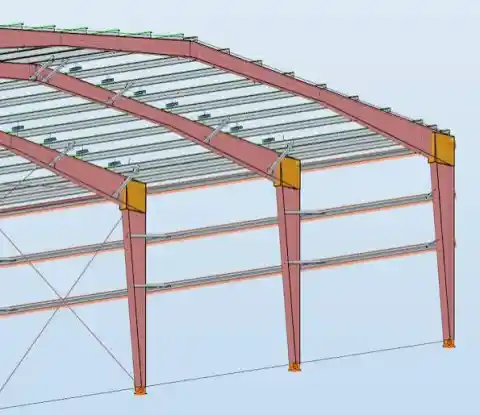
A pre-engineered metal building (PEMB) is a complete structural system — primary steel frames, secondary cold-formed members, and cladding — designed in a factory and bolted together on site. The core engineering advantage: tapered built-up I-sections place steel only where bending demand is highest, reducing total structural weight by 25–30% compared to conventional hot-rolled construction. The result is a building that costs 30–35% less, erects 50% faster, and spans up to 300 ft (90 m) column-free. This guide covers every technical layer an engineer or owner needs to design, specify, and build a PEMB correctly.
Pre-engineered metal buildings now account for roughly one-third of all new low-rise non-residential construction in the United States. The US market was valued at $12.98 billion in 2024 and is forecast to reach $27.1 billion by 2033 (Grand View Research). Understanding the design logic — not just the product brochure — is what lets engineers control quality, catch specification errors, and add value on any PEMB project.
📐 Table of Contents
- What Is a Pre-Engineered Metal Building?
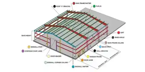
- Anatomy of a PEMB System
- Primary Framing System
- Secondary Framing: Purlins & Girts
- Cladding & Roofing Systems
- Design Loads & Code Compliance
- Wind Load Design (ASCE 7)
- Snow Load Design (ASCE 7)
- Seismic Design Considerations
- Foundation Design for PEMBs
- Connection Details
- PEMB vs Conventional Steel Construction
- Design & Manufacturing Process
- Erection Sequence
- Cost Data 2026
- Applications
- Advantages & Limitations
- FAQs
What Is a Pre-Engineered Metal Building?
A pre-engineered metal building is a complete structural kit: every primary column, rafter, purlin, girt, panel, clip, and fastener is factory-engineered, fabricated, and shipped as a numbered, sequenced assembly. Unlike conventional steel construction — where a structural engineer designs from scratch, a fabricator cuts and welds raw sections, and a contractor assembles on site — the PEMB manufacturer performs all three functions as a single source under one quality system.
The key structural innovation is the tapered built-up section. Instead of a uniform wide-flange shape (W-section), a PEMB rafter is welded from three plates (two flanges + one web) with web depth varying along the member length — deepest at the knee joint where bending moment peaks, shallowest near the ridge. This variable geometry follows the bending moment diagram, eliminating steel where it isn't needed. A 100,000 sq ft PEMB warehouse may use 30% less steel tonnage than a conventional W-section equivalent.
Anatomy of a PEMB System
Every pre-engineered metal building consists of three nested structural layers. Understanding which layer resists which load is the starting point for all technical specification and quality verification work.
① Primary Structural Framing
- Tapered built-up rigid frames (columns + rafters)
- End-wall frames (post & beam or rigid)
- Knee braces & base plates
- Crane girders (where specified)
- Material: ASTM A 572 Gr.50 / A 992 (Fy = 50 ksi)
- Fabrication: SAW welding, CNC drilling
② Secondary Structural Framing
- Roof purlins (Z or C cold-formed, ASTM A 570)
- Wall girts (Z or C cold-formed)
- Eave struts (structural transition at eave)
- Flange braces (lateral stability of rafters)
- Bridging angles (purlin spacing control)
- Gauge: 13–16 gauge; Fy = 50–65 ksi
③ Cladding & Roofing System
- Standing seam or screw-down roof panels
- Profiled wall panels (single / double / sandwich)
- Insulation (PIR, PUR, mineral wool)
- Ridge cap, corner trim, flashing
- Skylights & ventilation accessories
- Substrate: AZ50–AZ55 Galvalume® coated
④ Foundation System
- Isolated spread footings under each column
- Grade beam (perimeter concrete beam)
- Slab-on-grade (SOG) — typically 4–6 in. concrete
- Anchor bolts (ASTM F1554 Gr.36 or Gr.55)
- Not supplied by PEMB manufacturer
- Anchor bolt template critical for erection accuracy
Primary Framing System
The primary structural frame is the skeleton of the PEMB. It resists all gravity and lateral loads and transfers them to the foundation. Four frame types cover nearly all commercial PEMB applications:
Clear-Span Rigid Frame
Single-bay, no interior columns. Spans 40–150 ft (12–46 m). Tapered columns and rafters. Best for: warehouses, hangars, arenas, unobstructed floor plans.
Multi-Span Rigid Frame
Multiple bays with interior columns. Spans 150–300 ft+. More economical for very large footprints where interior columns are acceptable.
Modular / Single-Slope Frame
Single-slope rafter for drainage to one side. Common for additions, canopies, and buildings where all drainage must go to one wall.
Lean-To Frame
One end frames into an existing structure. Used for covered loading docks, additions, canopies, and shade structures attached to a main building.
Tapered Section Engineering
PEMB primary members are built-up welded I-shapes fabricated from individual plate elements. The web plate depth varies continuously — engineers call this a prismatic-variable section. Fabrication uses:
- CNC plasma or oxy-fuel cutting — web and flange plates cut to precise tapered profiles
- Submerged Arc Welding (SAW) — automated double-fillet welds join flanges to web; penetration, heat input, and weld size are process-controlled
- CNC drilling — connection holes punched or drilled to match erection bolt patterns exactly
- Shot-blasting & prime coat — SP-6 commercial blast standard; primer typically 1.5–2.0 mils DFT
| Primary Frame Parameter | Typical Range | Notes |
|---|---|---|
| Material Standard | ASTM A 572 Gr.50 / A 992 | Fy = 50 ksi minimum; Fu = 65 ksi |
| Column Depth at Base | 12–36 in. (varies) | Deepest at knee connection |
| Rafter Depth at Knee (Haunch) | 24–60 in. (varies) | Maximum bending demand location |
| Rafter Depth at Ridge | 8–16 in. (varies) | Minimum bending demand location |
| Flange Width | 4–10 in. (varies) | Wider flanges for lateral stability |
| Flange Thickness | 0.25–1.0 in. | Controls local buckling |
| Web Thickness | 0.1875–0.5 in. | Stiffeners required where h/tw > 2.24√(E/Fy) |
| Weld Type (SAW) | Double-fillet or partial penetration | Per AISC 360 Table J2.4 |
| Max Clear Span | ~300 ft (91 m) | Practical limit for rigid frame economy |
Secondary Framing: Purlins, Girts & Eave Struts
Secondary members span between primary frames to support the cladding and transfer wind, snow, and gravity loads to the primary system. They are cold-formed from coiled high-strength steel — not cut from hot-rolled sections — which makes them significantly lighter than equivalent hot-rolled members.
Purlins (Roof Secondary Members)
Purlins run perpendicular to primary frames across the roof slope. They support roof cladding and transfer gravity (dead + snow + live) and wind uplift loads. Standard profiles are Z-sections (preferred for continuous lapped spans) or C-sections (for simple spans at end bays). Key design parameters:
- Material: ASTM A 570 Grade 50 or 55 (Fy = 50,000–55,000 psi); some manufacturers use Fy = 65 ksi for higher-load applications
- Gauge range: 16 gauge (0.060 in.) to 12 gauge (0.105 in.) based on span and load
- Typical depth: 8 in. for standard bay spacing; 10–12 in. for heavy snow or longer spans
- Bay spacing: 20–25 ft standard; optimized to 5–8 ft purlin spacing within each bay
- Lapped Z-purlins: Overlapping 1.5× the purlin depth at interior supports provides continuous-beam moment continuity — standard PEMB practice to reduce required section size by 30–40%
- Web crushing at supports: Critical limit state — angle clip plates are used to prevent web crippling at purlin-to-frame connections
- Bridging angles: Intermediate bridging at mid-bay controls lateral-torsional buckling of the cold-formed section
Girts (Wall Secondary Members)
Girts perform the same function as purlins but for wall panels — they span horizontally between primary columns and transfer wind pressure and suction to the primary frame. Bypass girts (running continuously past columns on the outside face) are standard for wall panels. Inset girts (between columns) are used where a flush interior wall surface is needed.
Eave Strut
The eave strut is the structural element at the intersection of roof and wall — a critical transition member that simultaneously acts as the last roof purlin, first wall girt, and lateral bracing element. It is typically a C-section or Z-section with a formed lip that accepts both roof and wall panel systems. Eave strut misalignment or improper sizing is a common source of PEMB roof leaks and erection problems.
Cladding & Roofing Systems
| Cladding Type | Profile | Application | Thermal Performance | Notes |
|---|---|---|---|---|
| Single-Skin Screw-Down | 26-gauge ribbed | Economy warehouses unheated | Poor (no insulation path break) | Exposed fasteners; direct puncture of panel |
| Standing Seam Roof | 24-gauge Galvalume | Commercial / industrial standard | Moderate with blanket insulation | Hidden fasteners; thermal movement allowed |
| Insulated Sandwich Panel (PIR) | 40–200 mm core | Cold storage / controlled environments | U = 0.19–0.35 W/m²K | Factory-bonded; no site insulation installation |
| Mineral Wool Sandwich Panel | 50–150 mm core | High fire resistance applications | U = 0.20–0.40 W/m²K | Non-combustible; preferred in fire-rated assemblies |
| PBR Panel (Screw-Down) | 26-gauge | Agricultural / economy commercial | Blanket insulation required separately | R-value depends on added insulation |
Design Loads & Code Compliance
PEMB design must comply with the same structural codes as any steel building. The critical documents are:
| Standard | Scope | Authority |
|---|---|---|
| ASCE 7-22 | Minimum design loads (dead/live/wind/snow/seismic/rain/flood/ice) | Structural load determination — referenced by all US building codes |
| IBC 2021 | Building code referencing ASCE 7 and material standards | Adopted (with amendments) in most US jurisdictions |
| AISC 360-22 | Structural steel design (primary members — hot-rolled) | LRFD and ASD method; governs built-up sections |
| AISI S100-16 | Cold-formed steel design (secondary members) | Governs purlins / girts — not AISC |
| MBMA Design Practices Manual (2012) | Metal building industry standard design guidance | Industry reference; supplements AISC/ASCE |
| ASTM A 572 / A 992 | Primary steel material standard | 50 ksi minimum yield strength |
| ASTM A 570 / A 1011 | Cold-formed steel material standard | 50–65 ksi yield; purlins and girts |
| ASTM F1554 | Anchor bolt standard (Grades 36 / 55 / 105) | Foundation connection |
Design Load Types for PEMBs
- Dead Load (D): Self-weight of structural steel + roofing panels + insulation. Primary frame: 2–5 psf. Cladding: 1.5–3 psf.
- Collateral Load (CL): Superimposed dead loads — sprinklers, lights, HVAC units, catwalks. Must be defined by owner/specifier; typically 1–5 psf but can be 10+ psf for heavy equipment.
- Roof Live Load (Lr): 12–20 psf per ASCE 7 §4.9 based on tributary area and roof slope — for maintenance access, not snow.
- Snow Load (S): Per ASCE 7 Chapter 7 — site-specific ground snow load from ASCE 7 maps converted to roof snow load.
- Wind Load (W): Per ASCE 7 Chapters 26–27 — velocity pressure at eave height, applied to MWFRS and C&C zones.
- Seismic Load (E): Per ASCE 7 Chapters 11–12 — depends on Seismic Design Category (SDC) and Structural System.
- Crane Loads: Vertical (lifted load + bridge + trolley weight) + horizontal (20% of lifted + bridge for longitudinal; 10% of lifted + trolley for transverse). Must be provided by crane manufacturer as part of the design criteria.
Wind Load Design — ASCE 7-22
Wind is typically the governing lateral load for PEMB structures. Two design procedures apply: the Directional Procedure (Chapter 27) for Main Wind Force Resisting System (MWFRS) and the Envelope Procedure (Chapter 28) for low-rise buildings. PEMB manufacturers use Chapter 28 Envelope Procedure in most cases — it is calibrated specifically for low-rise buildings with h ≤ 60 ft.
ASCE 7-22 §27.3 — Design Wind Pressure: MWFRS (Directional Procedure)
p = qz × G × Cp − qi × G × Cpi
qz = 0.00256 × Kz × Kzt × Ke × V² (lb/ft²)
p = design wind pressure (psf) | qz = velocity pressure at height z (psf)
G = gust factor (0.85 for rigid structures) | Cp = external pressure coefficient
qi = velocity pressure for internal pressure | Cpi = internal pressure coefficient (±0.18 enclosed / ±0.55 partially enclosed)
Kz = exposure factor | Kzt = topographic factor | Ke = ground elevation factor | V = Basic Wind Speed (mph, Risk Category II map)
Wind Speed Selection (ASCE 7-22)
ASCE 7-22 provides ultimate (strength-level) design wind speeds mapped by Risk Category:
- Risk Category I (low hazard to human life): V ranges from 85–150 mph
- Risk Category II (standard): V ranges from 90–170 mph in continental US; up to 200+ mph in hurricane-prone regions
- Risk Category III/IV (essential facilities): V is 15–25 mph higher than Cat. II for the same location
Snow Load Design — ASCE 7-22 Chapter 7
ASCE 7-22 §7.3 — Balanced Roof Snow Load
ps = 0.7 × Ce × Ct × Is × pg
Minimum: pf = Is × pg (for pg ≤ 20 psf) | pf = 20 × Is (for pg > 20 psf)
ps = sloped roof snow load (psf) | pg = ground snow load from ASCE 7 Fig. 7.2-1 (psf)
Ce = Exposure Factor (0.7–1.3; fully exposed roofs reduce load, sheltered increase) | Ct = Thermal Factor
Is = Importance Factor (Risk Category I: 0.80; Cat. II: 1.00; Cat. III/IV: 1.10–1.20)
Special snow conditions for PEMBs:
- Unbalanced snow: Required for gable roofs with slope > ½:12 — leeward drift loads the downwind half while windward is swept bare. Governs many purlin and primary frame designs.
- Drift loads: Snow drifts against parapet walls, at roof steps, and around rooftop equipment. ASCE 7 §7.7–7.8 provides drift surcharge calculation methods. Critical for stepped roofs common in PEMB additions.
- Rain-on-snow surcharge: 5 psf added for pg < 20 psf in most jurisdictions.
Seismic Design Considerations for PEMBs
Most PEMBs qualify as low-rise, single-story structures — their seismic behavior is governed by ASCE 7 Chapter 12 and the structural system classification determines the Response Modification Factor (R) and permitted design methods.
| PEMB Lateral System | ASCE 7 System | R Factor | Ω₀ | Cd | Limitation |
|---|---|---|---|---|---|
| Ordinary Steel Moment Frame (OMF) | ASCE 7 Table 12.2-1 | 3.5 | 3.0 | 3.0 | Not permitted in SDC D/E/F |
| Special Steel Moment Frame (SMF) | ASCE 7 Table 12.2-1 | 8.0 | 3.0 | 5.5 | Permitted all SDCs; prescriptive detailing per AISC 341 |
| Steel Buckling-Restrained Braced Frame (BRBF) | ASCE 7 Table 12.2-1 | 8.0 | 2.5 | 5.0 | Permitted all SDCs |
| Ordinary Concentrically Braced Frame (OCBF) | ASCE 7 Table 12.2-1 | 3.25 | 2.0 | 3.25 | SDC A-C only; some PEMB manufacturers default to this |
| Special Concentrically Braced Frame (SCBF) | ASCE 7 Table 12.2-1 | 6.0 | 2.0 | 5.0 | Permitted all SDCs |
Foundation Design for PEMBs
The PEMB manufacturer provides column reaction loads (vertical, horizontal, and moment at base) for all design load combinations. The geotechnical/structural engineer of record designs the foundation using these reactions against the site soil bearing capacity from the geotechnical report.
Anchor Bolt Design — Critical Interface
Anchor bolts are the most critical interface between the PEMB structure and the foundation. PEMB columns are typically pinned-base (moment = 0 at base — reduces footing size but requires braced bays for lateral resistance) or fixed-base (moment transfer to footing — increases footing cost but allows reduction in lateral bracing).
| Anchor Bolt Parameter | Pinned-Base Column | Fixed-Base Column |
|---|---|---|
| Bolt Pattern | 2–4 bolts at flange centerlines | 4–8 bolts at wider base plate gauge |
| Governing Load | Axial compression + shear | Tension uplift + moment + shear |
| Standard Material | ASTM F1554 Grade 36 | ASTM F1554 Grade 55 or 105 |
| Base Plate Design | Per AISC Design Guide 1 | Per AISC Design Guide 1 (moment connection) |
| Footing Size | Smaller — eccentric moment = 0 | Larger — resist overturning moment |
| Typical Footing Depth | Frost depth + 6 in. min | Frost depth + bearing + moment arm |
Connection Details
All major PEMB field connections are bolted, not welded — this is what enables rapid erection by non-specialized crews. Key connections:
- Knee (Column-to-Rafter): Moment connection using multiple high-strength bolts (ASTM A325 or A490) through end plates. Designed for the full plastic moment capacity of the section. This is the most highly loaded connection in the building.
- Ridge (Rafter-to-Rafter): End-plate bolted moment connection at building centerline. In clear-span frames, the ridge connection carries the full wind/snow bending demand transferred from both sides.
- Base Plate (Column-to-Foundation): Base plate welded to column in factory; field-bolted to anchor bolts. Pinned or moment-resisting depending on design.
- Purlin-to-Frame: Cold-formed Z/C purlin bolted through angle clip to primary frame flange. Self-drilling screws (TEK screws) connect purlins to each other at lapped joints.
- Panel-to-Purlin: Standing seam clips engage roof panels without penetrating panel surface; screw-down systems use #14 self-drilling screws with EPDM-sealed heads at every purlin.
- X or V Rod Bracing (End Bays): Rods or cables provide diagonal bracing in end bays to transfer longitudinal wind into the foundations. Pretensioned using turnbuckles.
PEMB vs Conventional Steel Construction
| Factor | Pre-Engineered Metal Building | Conventional Steel Construction |
|---|---|---|
| Design Time | Days to weeks (proprietary software + standard systems) | Weeks to months (custom design from scratch) |
| Fabrication Lead Time | 6–8 weeks after order confirmation | 14–20 weeks for raw material + fabrication |
| Total Schedule | 8–12 weeks (concurrent foundation + fabrication) | 20–26 weeks sequential |
| Steel Weight | 30% lighter (tapered variable sections) | Standard W-sections — conservative weight |
| Cost (Low-Rise) | $25–$45/sqft installed shell | $45–$80/sqft installed shell |
| Clear Span | Up to 300 ft economical | Unlimited but very costly beyond 200 ft |
| Expandability | Excellent — add bays longitudinally | Difficult — requires new analysis |
| Complex Geometry | Limited — standard configurations | Unlimited — fully custom |
| Multi-Story | 1–2 stories max economically | Unlimited — designed for high-rise |
| Quality Control | Factory-controlled environment; CNC fabrication | Field welding variability |
| Design Responsibility | Single source — manufacturer is EOR for structure | Split — engineer designs; contractor builds |
| Fire Rating | Requires spray-on or board fireproofing | Same — both require fireproofing for occupancy |
| Aesthetic Flexibility | Limited without architectural cladding overlay | Higher — any cladding, shape, expression |
Design & Manufacturing Process
Understanding the manufacturer's design process helps engineers know when they can make changes, what information the manufacturer needs, and where the critical quality checkpoints are.
- 11. Design Criteria ConfirmationOwner/specifier provides: clear span, eave height, bay spacing, roof slope, all design loads (wind speed, ground snow, SDC, live/collateral loads), occupancy/use, required openings, and code edition. This is the most critical step — errors here propagate through every downstream deliverable.
- 22. Structural Analysis & OptimizationManufacturer's engineers run proprietary software integrating load analysis, section optimization, and AISC 360/AISI S100 code checks. Tapered section profiles are optimized to minimize steel tonnage while meeting all limit states.
- 33. Approval Drawings IssuedManufacturer issues General Arrangement drawings showing frame geometry, column locations, bay spacing, roof slope, eave heights, and primary reactions. Engineer of Record reviews and stamps. This is the legal design approval checkpoint.
- 44. Shop Drawings & FabricationCNC programs generated from structural model. Plates cut, welded (SAW), drilled, and labeled. Secondary members roll-formed. All components shot-blasted and primed. Parts bundled and tagged per erection sequence.
- 55. Foundation Package ReleasedManufacturer issues anchor bolt plan and column reaction summary. Site engineer designs footings and slab-on-grade using these reactions. Foundation construction can parallel fabrication — this schedule overlap is where PEMB delivers schedule advantage.
- 66. ShipmentNumbered, sequenced components shipped as a kit. Erection manual included with piece-mark cross-reference. Delivery to site verified against shipping list before erection begins.
Erection Sequence
Anchor Bolt Verification
Survey all anchor bolt positions against the certified anchor bolt plan before erection begins. Verify bolt projection height and thread engagement. Do not proceed if bolts are out of tolerance — correct at foundation level, not at structure.
First Rigid Frame Erection
Set and plumb first interior rigid frame. Install temporary cable or pipe bracing immediately — the isolated frame has zero lateral stability without bracing. This is the highest-risk moment of PEMB erection; wind-induced collapse of unbraced frames is a documented failure mode.
Sequential Frame & Purlin Installation
Erect subsequent frames and immediately install roof purlins between frames. Purlins serve as longitudinal ties that stabilize each new frame as it is added. Maintain temporary bracing until permanent bracing is installed.
Permanent Bracing System
Install X-rod or cable bracing in designated end bays. Tension rods to manufacturer's specified pretension. Install flange braces from rafter to purlin — these brace the compression flange of the rafter against lateral-torsional buckling.
Roof Panels & Accessories
Install roof panels starting at eave, working upslope. For standing seam: snap panels into clips; seam mechanically by seaming machine. For screw-down: install fasteners at correct centers per manufacturer's fastener schedule (critical for uplift resistance).
Wall Girts, Panels & Finishing
Install wall girts, wall panels, framed openings, doors, windows, corner trim, ridge cap, downspouts, and gutters per erection manual. Final inspection: verify all bolts are snug-tight or fully tensioned per connection specification.
Cost Data 2026 — Pre-Engineered Metal Buildings (USA)
| Building Size | Sqft | Package Cost | Foundation Cost | Erection Cost | Total Shell Cost | |||||||||
|---|---|---|---|---|---|---|---|---|---|---|---|---|---|---|
| 30×40 ft | 1 | 200 | $17 | 000–$26 | 000 | $8 | 400–$12 | 000 | $8 | 400–$12 | 000 | $40 | 800–$50 | 400 |
| 50×100 ft | 5 | 000 | $70 | 000–$90 | 000 | $25 | 000–$40 | 000 | $25 | 000–$40 | 000 | $130 | 000–$170 | 000 |
| 100×200 ft | 20 | 000 | $280 | 000–$360 | 000 | $80 | 000–$160 | 000 | $80 | 000–$160 | 000 | $440 | 000–$680 | 000 |
| 200×400 ft | 80 | 000 | $1.1M–$1.4M | Custom Quote | Custom Quote | Custom Quote |
PEMB Applications
| Application Type | Typical Clear Span | Typical Eave Height | Special Requirements |
|---|---|---|---|
| Distribution Warehouse | 150–300 ft | 28–40 ft | High collateral load; dock doors; crane provisions |
| Aircraft Hangar (T-Hangar) | 40–60 ft per unit | 14–20 ft | Sliding/folding door header; no interior columns |
| Aircraft Hangar (Corporate) | 150–250 ft | 30–50 ft | Long clear span; high wind/seismic demand |
| Manufacturing Facility | 80–200 ft | 20–40 ft | Heavy crane loads; overhead utilities; blast/explosion provisions |
| Cold Storage / Freezer | 60–150 ft | 30–40 ft | Insulated sandwich panel; thermal break at base; condensation control |
| Retail / Commercial | 50–150 ft | 16–24 ft | Architectural facade over PEMB frame; show-room height |
| Agricultural Storage | 40–100 ft | 12–20 ft | Economy specification; open sides acceptable |
| Sports Arena / Recreation | 100–250 ft | 24–40 ft | Long span; spectator loading; acoustics; HVAC provisions |
| Data Center | 60–150 ft | 16–24 ft | Enhanced seismic; backup power; security; heavy floor loading |
| Military / Government | 80–200 ft | 20–30 ft | UFC (Unified Facilities Criteria) compliance; force protection |
PEMB Structural Engineering Services — Design, Review & Specification
Structural analysis and review of pre-engineered metal building designs — primary frame sizing, foundation reaction verification, anchor bolt design, and ASCE 7 load compliance checking for warehouse, industrial, and commercial PEMBs.
View Structural Engineering Portfolio →Advantages & Limitations
✅ Advantages of Pre-Engineered Metal Buildings
- 30–35% cost saving vs equivalent conventional steel
- 50% faster total project schedule (parallel fabrication + foundation)
- 25–30% lighter steel weight via tapered section optimization
- Factory quality control — CNC fabrication, controlled welding environment
- Single-source responsibility for structural system
- Column-free spans up to 300 ft for unobstructed operations
- Future expandability — add bays longitudinally at low cost
- 98% steel recyclability at end of life
- Crane integration up to 200+ ton capacity
- Standardized connection details — faster and safer erection
⚠️ Limitations & Challenges
- Design freeze at fabrication — changes after shop drawings are costly
- Limited to 1–2 stories for cost-effective application
- Standard configurations — complex or irregular plans require custom pricing
- Condensation risk without proper vapor barrier and insulation detailing
- Acoustic performance poor without additional treatment
- Corrosion risk in coastal / chemical / high-humidity environments
- Aesthetics limited without architectural cladding overlay (adds 20–40% cost)
- Fire rating requires applied fireproofing — not inherent in steel structure
- OCBF bracing not permitted in SDC D/E/F — seismic upgrade adds cost
- Anchor bolt errors are expensive to correct after foundation poured
Frequently Asked Questions
Conclusion: Engineering a PEMB the Right Way
A pre-engineered metal building is not a commodity product — it is a custom-engineered structural system that happens to be manufactured in a factory. The engineering decisions that determine its performance happen at the design criteria stage, not the erection stage. Specifying the wrong wind speed, underestimating collateral loads, selecting the wrong seismic system for the SDC, or mislocating anchor bolts are all errors that range from expensive to catastrophic.
The engineers who get the most value from PEMBs are the ones who understand both sides of the interface: the manufacturer's design logic (tapered sections, AISI cold-formed design, proprietary connections) and the site-specific structural demands (ASCE 7 loads, local code amendments, geotechnical conditions). That combined knowledge is what produces a building that performs reliably for 50+ years at the lowest lifecycle cost.
For deeper technical resources on structural steel design, see our guide on ETABS vs STAAD Pro: Which Structural Analysis Software Should You Choose, the Structural Health Monitoring Complete Guide, and AI in Structural Engineering: BIM Integration and ML Analysis.
Be the first to comment.